

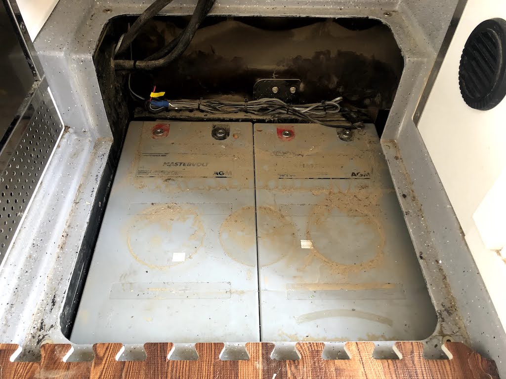
Molly came with two 270 Ah AGM batteries from Mastervolt(1). These are located in the battery box which is an ideal location, being low and in the center of the truck, literally between all four wheels. And although these batteries have served us well and generally got the job done, on a few occasions they ran flat and we had to start the engine and charge them from the alternator. This happened when we were either under trees for several days or when snow covered the solar panels.
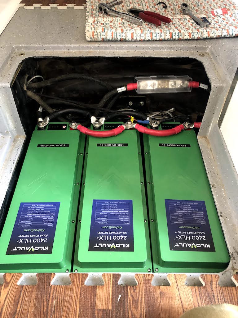
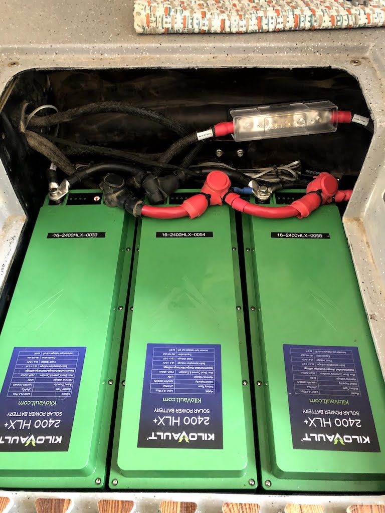
So, we decided it was time to upgrade our house batteries with higher charge capacity and at the same time change the technology from AGM to Lithium Iron Phosphate (LiFePO4). We choose to install three 200 Ah Cold Rated HLX+ series batteries from Kilovault.
Based on the before and after specifications, the new batteries offer twice the capacity, operate in the same temperature range, take about the same space and are half the weight. There are two notable negatives, being that these lithium batteries are about twice the cost of Mastervolt AGMs and the maximum current draw is a little less at 450 Amps vs 510 Amps that we originally had.
Before
Total Capacity : 540 Ah with approximately 270 Ah usable. For AGMs, the recommended deep of discharge is 50% to maintain the life of the battery.
Operating Range: –20 to 55ºC / –4 to 131ºF(2)
Space Required: 522 mm x 536 mm x 226 mm (LxWxH)
Weight: 146 kgs (322 lbs)
Maximum Continuous Current Draw: 510 Amps
After
Total Capacity : 600 Ah
Operating Range: –20 to 55ºC / –4 to 131ºF
Space Required: 505 mm x 517.5 mm x 255 mm (LxWxH)
Weight: 71 kgs (178.5 lbs)
Maximum Continuous Current Draw: 450 Amps
Battery Box
There were two reasons that led us to choose the Kilovault batteries, and both of these reasons involved the battery box.
First, our battery box is located on the outside of the truck, and when it gets cold outside, well, it also gets cold in the battery box. And lithium batteries really do not like to be charged when the temperature of the internal lithium cells fall below freezing. The Kilovault batteries are cold rated and have an internal heater which automatically turns on to raise the temperature of the battery when it is too cold, and once a suitable internal temperature is achieved, only then will the internal Battery Management System (BMS) allow charging of the lithium cells to occur. Other companies like Lithionics Battery, Battle Born and Relion all offer similar cold rated and self heating batteries, so this is not unique to Kilovault. It is also possible to insulate and heat the battery box independently, but this is more hassle and requires space in the battery box for the heating equipment.
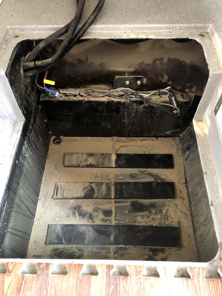
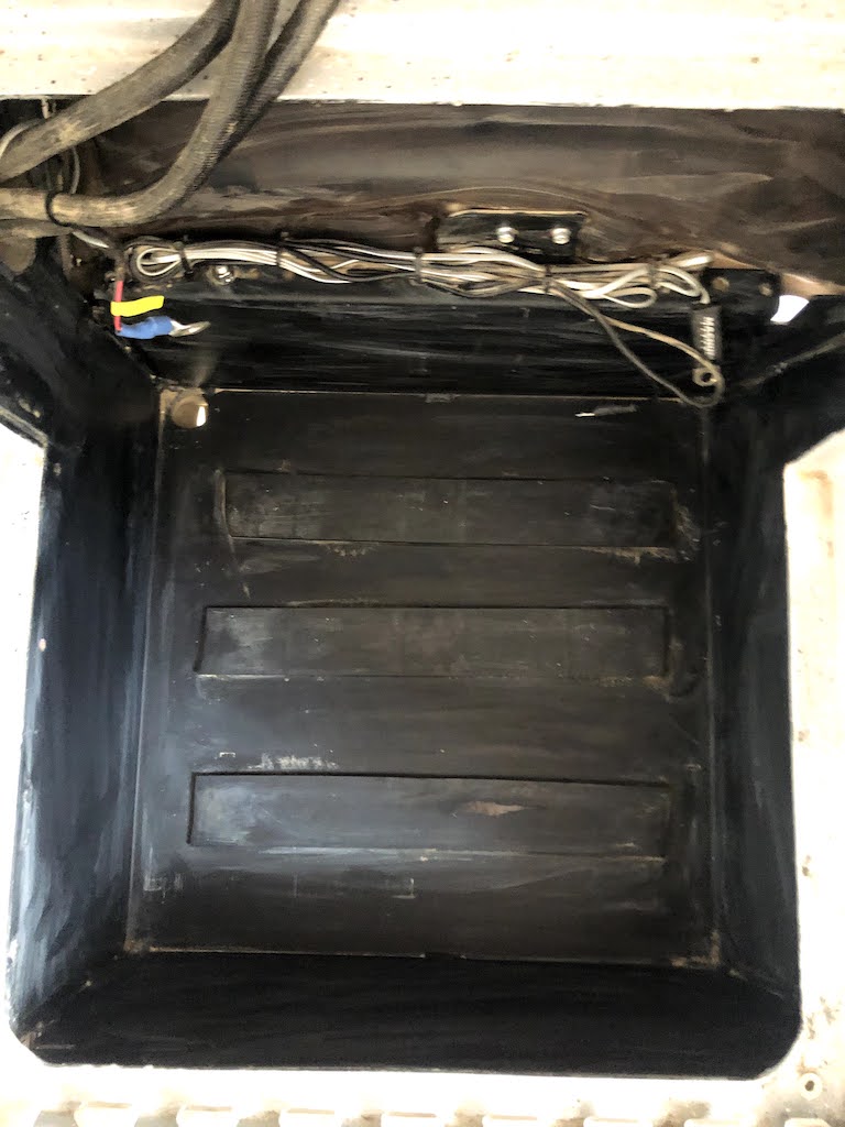
The second challenge with of battery box is its compact size and sturdy construction. Whatever batteries we choose need to fit into the battery box, as it would a huge effort to change the size of the battery box. The available space in the battery box is 560mm x 537mm x 270 mm (LxWxH).
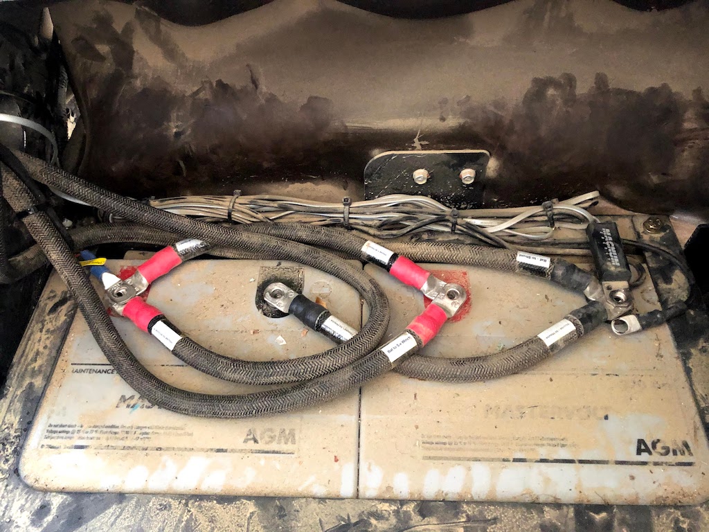
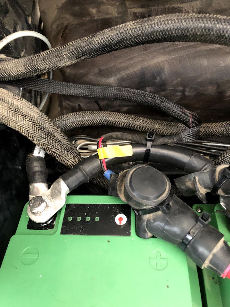
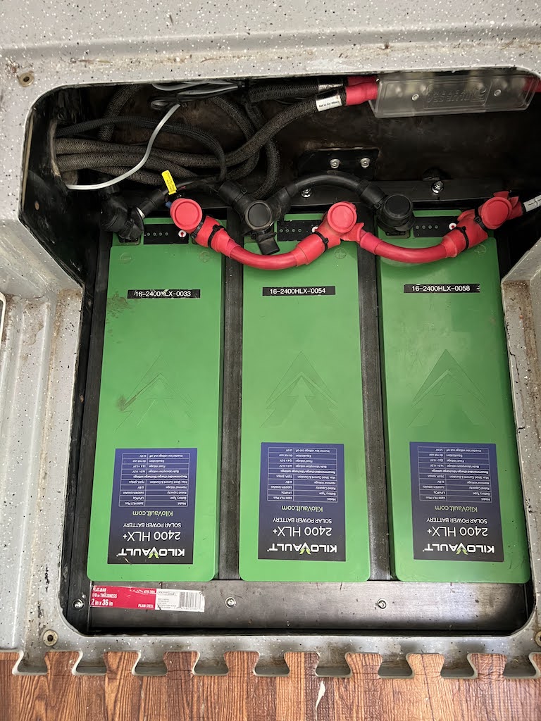
After searching the internet for many hours and considering many options, the Kilovault product allowed us to fit 600 Ahr into the available and sometimes cold space. Our battery box is also not fully weather sealed, so dust and water can get in there. The Kilovault HLX+ series batteries have an IP55 rating, meaning that even as dust and water enters the battery box, it will not be a problem for the batteries as they are sufficiently sealed. The photos off the old battery confirms that dust gets into the battery box.
We choose not to insulate the battery box from the cold (or the heat). The ambient temperature is unlikely to get above 55ºC, so this is not going to help to keep them cool, in fact will make it worse. The internal BMS will shut off the batteries above 65ºC. And as they are cold rated batteries, so less worried about protecting against cold conditions.
Battery Capacity
We spent many hours wringing our hands and thinking about how much battery capacity we need. And the size of the batteries is related to the amount of solar generation we have. See our Solar post for more details on why we think 600 Ahr is the right choice for us.
It should be noted, that Victron Energy makes a very compact 200 Ahr battery, and we could fit 4 of these into our battery box, for a whopping 800 Ahr. However, these batteries are not cold weather rated. Clearly bigger capacity, but the improvement in capacity is not worth the loss of cold weather rating.
Battery Commissioning
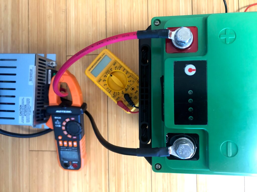
The batteries are shipped in a discharged state, due to shipping regulations in the US. So, once received, we charged them up as per the manufacturers commissioning procedure. For this task we used an Iota Engineering DLS-45 battery charger, being the one recommended by Kilovault.
Adding a Fuse
The original AGM battery setup did not include a battery fuse to protect the wiring. Since we are already changing things, we decided to add a protective fuse on the positive feed. The fuse selected is a 500 Amps ANL fuse. And this goes into a protective ANL Fuse Block, from Blue Sea (part number 5503).
Technically the winch can draw up to 507 Amps when operating at the full 16,500 lbs and on the first layer of the drum. We will also run the engine while winching, so the alternator and truck batteries will also be contributing to the power draw. Each Kilovault HLX+ series lithium batteries can operate at 150 Amps sustained (so 3 batteries total of 450 Amps). And the Kilovaults internal BMS has over current protection when exceeding 210 Amps, just in case.
All of the existing wiring and isolators installed by Earthcruiser® will be retained. New colour-coded 8 inch connector 4/0 AWG connector cables where purchased to string the three batteries in parallel.
The Installation
The install took about 2 hours to complete. During the process we realized that
- Need some more battery terminal shrouds. And need to match up the colours correctly.
- Need a good way to secure the batteries.
- Need a good way to secure the fuse holder.
These are all things that can be done in the next attempt.
Programming the Solar Charge Controller
The Kilovault battery manual recommends a 3 stage charging configuration of fast Bulk phase, followed by a very short Absorption (Acceptance) phase and then a float phase and with no equalization phase. After a quick call to Roy over at Kilovault technical support, confirmed that Bulk would be 14.1 volts and Float would be 13.6 volts.
However our Blue Sky Solar charger is not able to limit the Absorption phase to under 2 minutes, so instead we configured the solar charge controller to skip the Absorption phase altogether. More details on this below with the final configuration.
- During the Bulk phase the solar charge controller will send as much current to the batteries as possible. In reality, the size of our solar panels limits this to about 25 Amps maximum.
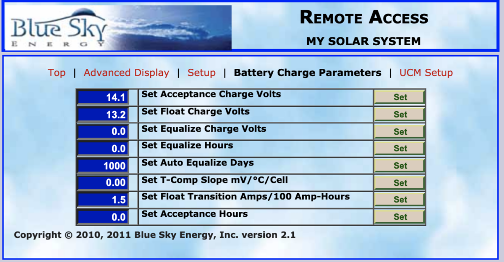
- Once the voltage of the batteries reach the Absorption (Acceptance) Charge Voltage setpoint, current is reduced as necessary to control the Absorption (Acceptance) Voltage. We set the Acceptance Charge Volts setpoint 14.1 volts. Earlier versions of the Kilovault manual had recommended 14.0 volts.
- Having said this, the Kilovault batteries do not like being in the Absorption phase for more than 2 minutes. And our controller only allows the time to be set in increments of a tenth of an hour (or increments of 6 minutes), in the range of 0 to 10 hours. So, we set the Acceptance Hours for 0 minutes, instead of 6 minutes. What this means is once the Absorption phase is triggered at 14.1 volts the controller immediately transitions to the Float phase.
- A short Absorption phase for lithium is useful to equalize the voltages across each cell. We will keep an eye on the cell voltages, as see if they equalize without an Absorption phase.
- Ryan at Blue Sky technical support also suggested that a 6 minute equalization phase at 14.1 volts every 30 days might make sense to equalize the cells.
- The Sets Float Transition Amps per 100 Amp-Hours is disabled by setting it to 0.0 Amps, with the transition from Bulk to Absorption/Float controlled by the timer only.
- Kilovault technical support recommended a float voltage of 13.6 volts, although the manual recommends 13.4 volts. Decided to go with 13.6 volts.
- Temperature compensation had to be disabled, so Set T-Comp Slope mV/°C/Cell was set 0.0.
There is no re-bulk voltage setting on our solar charge controller to trigger transition from Float back to Bulk charging. However, because the sun goes down every night, the controller transitions to Off mode at night and then in the morning when the sun comes back up, the controller transitions from Off to Bulk charge mode. Switching off the controller is another way to manually force a transition from Float mode to Bulk charging mode.
Also we noticed that while the solar charge controller is in Float mode, occasionally the batteries can go into Standby mode. I believe this is because the solar panels can supply sufficient power for the background load, being typically 60 to 90 watts. When the drain on the three batteries is less than 600 to 750 mAmps, or about 9 Watts, then the batteries will go into standby. Only when the power demand exceeds what the solar panels can generate, will the batteries start discharging to make up the difference.
if the batteries go into standby mode, the easiest way to force back to normal operations is by starting the truck engine and engaging the alternator. But this does not always work. Kilovault has a software upgrade coming for the batteries, which might fix all of this battery standby stuff.
Programming the Inverter/Charger
Programming our Magnum inverter/charger was even more difficult to sort out than our solar charge controller. And not even sure it is setup in the best possible configuration. There is a software upgrade available for our Inverter to better support lithium batteries, but of course we do not have the upgrade. The only good news is that we hardly ever use the Inverter/Charger as the goal is to mainly be “off-grid” and away from places that have power.
After talking to Kilovault, they advised that the settings in their manual is assuming the inverter/charger is wall mounted and constantly charging, which is not the situation we have in Molly. And we also have a solar charge controller. So, the advice was to use common sense based on the needs at the time, what the demand will be on the batteries in the coming days and what the current state is of the batteries. In the rare event we connect to shore-power, we will become human controllers and will manage the batteries manually.
There are two modes at our disposal that can be used, CC/CV and Custom. CC/CV is Constant Current/Constant Voltage and is good for bulk recharging. In bulk charge mode, we typically limit the DC current to 40 Amps to prevent the charger heating up too much. While Custom mode is configured to automatically keep the batteries topped up. Both modes can be initiated through the control panel. Here are the settings we have for the Custom mode.
- Maximum Charge Amps = 40 ADC (01D)
- Search Watts = 5W (02A)
- Low Battery Cutoff Setting = 12.3 volts (02B)
- AC Input Amps = 15 A (03A)
- VAC Dropout = 85 VDC (03B)
- Battery Type = Custom (03C)
- Set Absorb Volts = 14.1 Volts
- Set Float Volts = 13.6 Volts
- Set Equalization Volts = 14.0 Volts
- Set Equalization Done Time = 0.1 Hours
- Absorb Done Amps = 12 ADC (03D)
- Max Charge Rate 100% (03E)
- Set Max Charge Time = 12.0 Hrs (03F)
- Final Charge Stage = Silent (03G)
- Equalization Reminder Days = OFF (03H)
Alternator
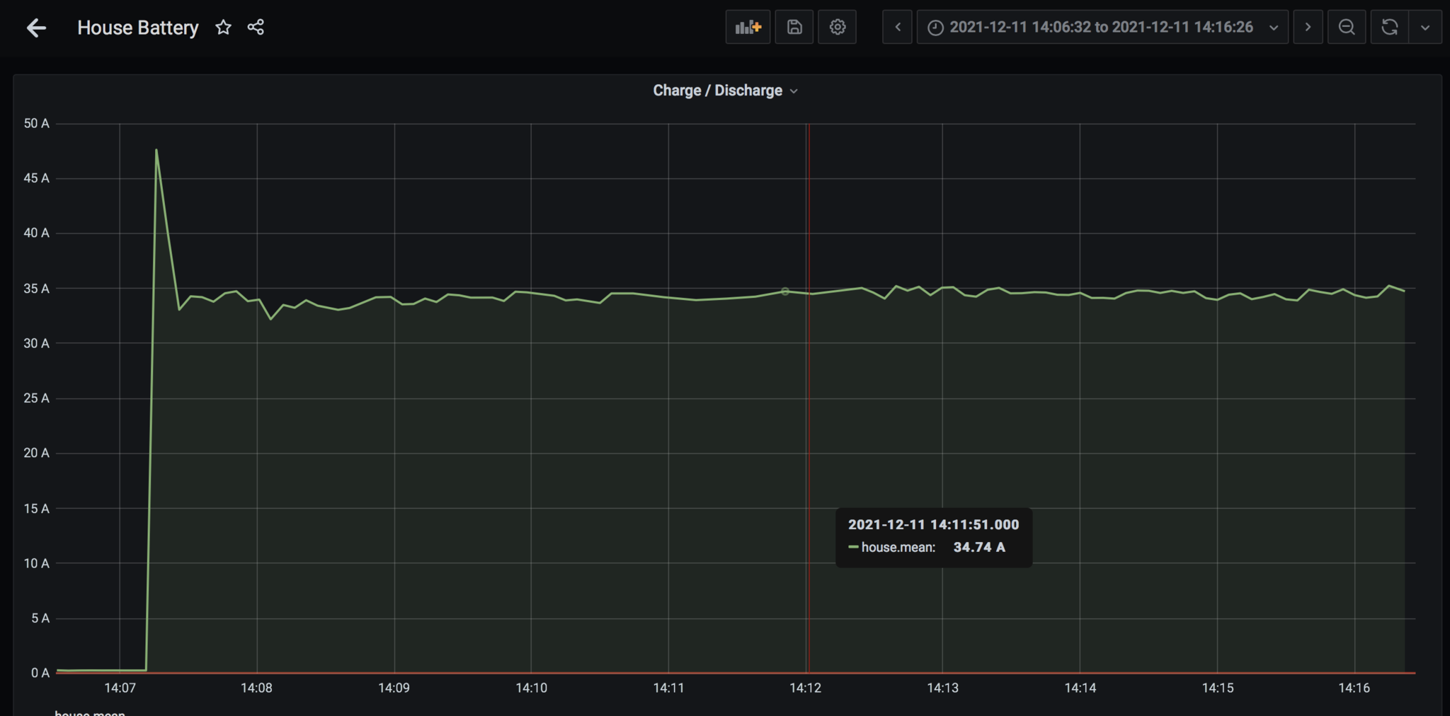
Our alternator can be used to charge the Kilovault batteries. Molly is fitted with a Bosch 0 124 525 216 alternator which has an internal regulator with a nominal output of 14.5 ± 0.25 volts and a maximum output rating of 140 Amps. When the truck engine is at idle, the alternator produces approximately 35 Amps, which increases to 42 Amps at 2,000 RPMs. The cost to generate electricity via the engine at idle is around $8 per kwhr, and is therefore a very expensive way to charge the batteries.
When the lithium batteries are not fully charged, it is safe (in theory) to direct connect the truck start batteries to the lithium house batteries via the emergency parallel switch in the electrical cabinet. The voltage produced by the alternator could damage the lithium batteries when they are near the end of their charge cycle.
We had plans to add a Renogy 20 Amps(3) DC to DC On-board Battery charger between the truck start batteries and the house batteries. The chemistry of the two battery banks are different, lead acid vs lithium, and each chemistries like to be charged in slightly different ways. The truck start battery is charged from of the alternator while the lithium house batteries will be charged from the DC to DC battery charger using the alternator as an input power source.
Included in the circuit is a BEP DVSR (digital voltage sensitive relay) in the circuit which only engages when the alternator is running, to prevent the DC to DC battery charger from draining the truck start batteries. The DVSR can be overridden from a switch in the front cab, which effectively becomes a manual on/off switch for the DC to DC battery charger. The DC to DC battery charger has a 12 volt input which can be wired to the ignition circuit to prevent the DC to DC battery charger from operating if the ignition is off. But we wired this input to the output of the DVSR relay, ensuring that charging only occurs when the engine and alternator are running.
In summary the DVSR ensures that we do not accidentally drain the truck start batteries and the DC to DC battery charger ensures we do not accidentally damage the lithium batteries and has the added benefit that it allows us to fully charge the lithium batteries from the alternator.
The above plans are on hold for the moment. The design is done, we purchased the Renogy charger and we even made and installed the mounting bracket. It only requires a few hours to to wire it all up. However, the current system works well enough, so we will probably never wire up the Dc to DC battery charger.
Retaining Bracket for the Batteries
After procrastinating for a year, finally made a retaining bracket by assembling various metal bars from the local hardware store.
- 4ft of 1 inch x 1/8th flat bar. Used to make 4 lengths running parallel with the batteries and between them.
- 3ft of 2 inch by 1/8th flat bar. Used to hold down one end of the above bars.
- 3ft of 1.25 inch x 1/8th flat bar. For the other end.
The bars were cut to size are arranged to securely hold down the batteries. Amazingly no new holes had to be drilled in the battery box. A few rivet nuts completed the job.
Future Considerations
Seriously thinking about moving to a single stage charging strategy. As a general statement, Lithium batteries prefer not to be operated at either extreme of their State of Charge (0% or 100%). This new strategy would involve disabling the float stage from the Solar Charge Controller when excess solar is available.
Installation of New Batteries

One Year Later

Future
One day we might add a dc-to-dc charging. Below is the proposed design.
Note 1 : The Product Code is 62002700
Note 2 : Capacity is reduced in cold weather.
Note 3 : Renogy recommends the 20 Amp DC to DC batter charger if your alternator is rated less than 160 Amps, which ours is.